Inside the wave field
Three numerical examples from my 2025 paper on a meshless, high-order finite-difference solver for the cold plasma wave equation. Select a figure to open it at full resolution.
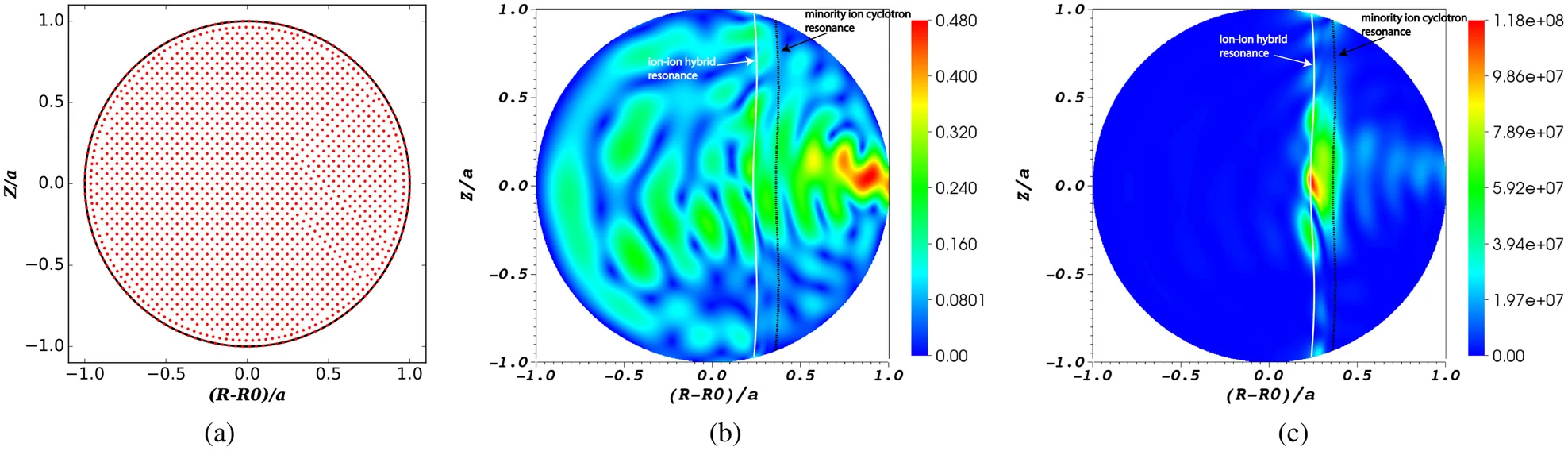
Figure 3: ion cyclotron heating
A mock-up tokamak example with an outboard-launched fast wave. Panels show (a) an illustrative point cloud, (b) electric-field strength, and (c) time-averaged absorbed power. The point cloud shown is less dense than the one used for the field calculation.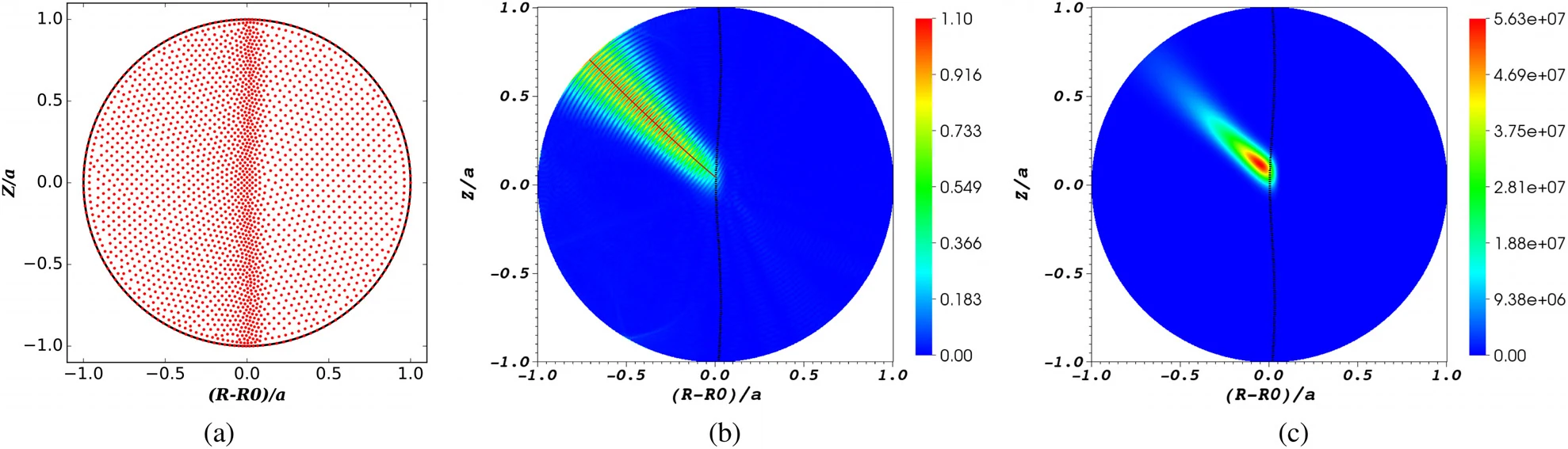
Figure 4: electron cyclotron heating
An inboard-launched X-mode example in a mock-up tokamak. Panels show (a) the point cloud, (b) electric-field strength with a ray-tracing comparison, and (c) absorbed power. These examples use scaled-down plasma parameters.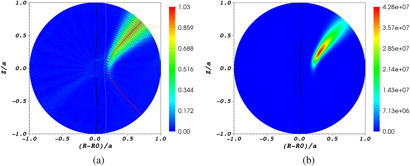
Figure 5: a beam that can’t reach the resonance
The same plasma with the antenna moved to the outboard side. Panels show (a) electric-field strength, with the ray-tracing path in red and the X-mode cutoff dashed in white, and (b) absorbed power. The wave is partly absorbed and reflected near the cutoff but cannot tunnel through to the resonance layer.Source: J. A. Spencer, V. A. Svidzinski, J. S. Kim, L. Zhao and S. A. Galkin, “An implementation of a high-order generalized finite difference method for solving the time-harmonic cold plasma wave equation in toroidal geometry,” Physics of Plasmas 32, 063902 (2025). © 2025 the authors. Reused under CC BY 4.0. Figures are extracted unaltered from the published PDF at their full embedded resolution. The homepage card uses a circular crop of Fig. 3(b), enlarged with AI upscaling (Real-ESRGAN) for sharp display on high-density screens. The animated field at the top of the homepage is an illustration, not output from this solver. No endorsement implied.